STMicroelectronics L298N Dual H-Bridge Motor Driver Module
৳ 170.00৳ 200.00 (-15%)
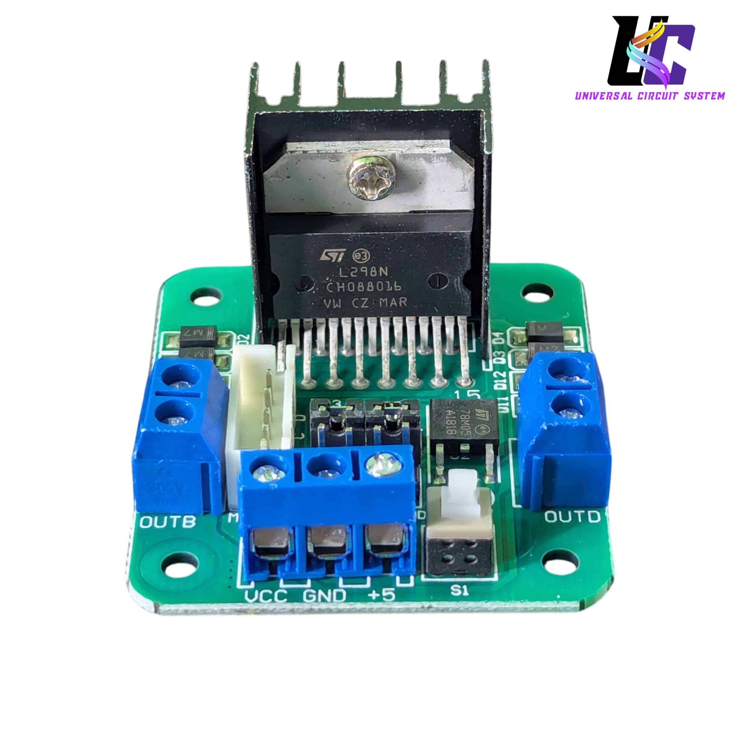
This is a high-power STMicroelectronics L298N dual H-bridge motor driver module designed for precision robotics and motor control prototyping [Image Context]. Operating across a wide 5V to 35V DC range, it can drive two independent brushed DC motors or one 4-wire stepper motor at up to 2A per channel continuous load [Image Context]. Outfitted with a heavy-duty aluminum finned heat sink, on-board 5V logic step-down regulator switch, and secure screw-terminal connection block nodes, this module pairs perfectly with Arduino or Raspberry Pi smart car systems
## Product Overview
The Universal Circuit System L298N Dual H-Bridge Motor Driver Module is an industry-standard, high-power motor control platform designed for precision robotics, automated machinery, and micro-controller prototyping [Image Context]. Driven by a high-voltage, high-current STMicroelectronics L298N dual H-bridge driver IC, this robust module enables microcontrollers like Arduino, Raspberry Pi, or ESP32 to safely manipulate the speed and rotational direction of heavy inductive loads [Image Context]. It isolates delicate digital logic chips from high-amperage spikes while providing a continuous, reliable muscle drive system for robotic vehicles.
——————————
## Design & Performance Features
* Dual H-Bridge Driver Architecture: Houses two independent internal H-bridge circuits [Image Context]. This structural layout can drive two brushed DC motors simultaneously (with independent speed and forward/reverse direction parameters) or manage one 4-wire, 2-phase stepper motor in full-step or half-step configurations.
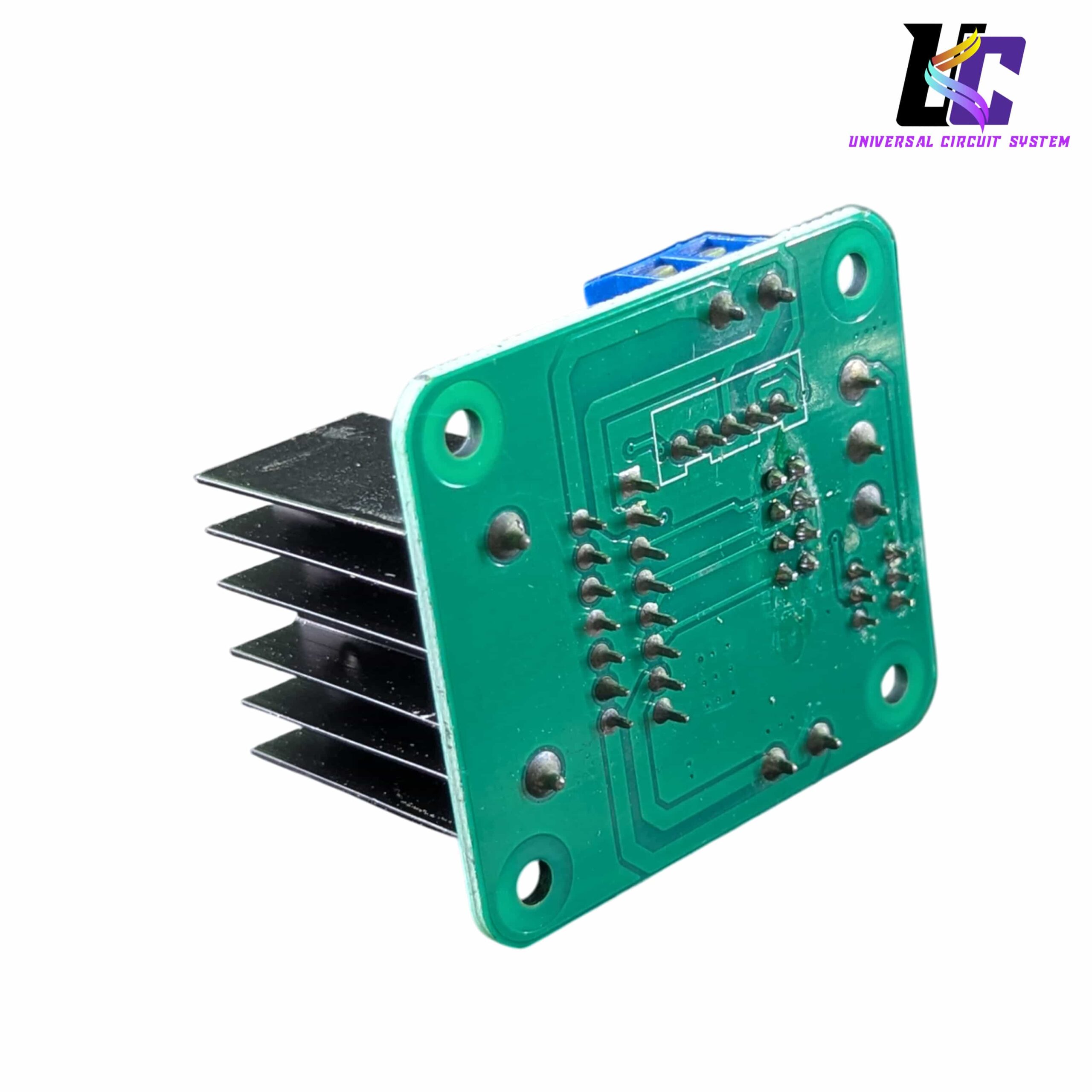
* Pre-Installed Finned Aluminum Heat Sink: The L298N multi-watt package is bolted directly to a thick, black-anodized aluminum cooling fin assembly [Image Context]. This block rapidly dissipates internal thermal buildup generated by continuous heavy current loads, preventing thermal cutout failures.
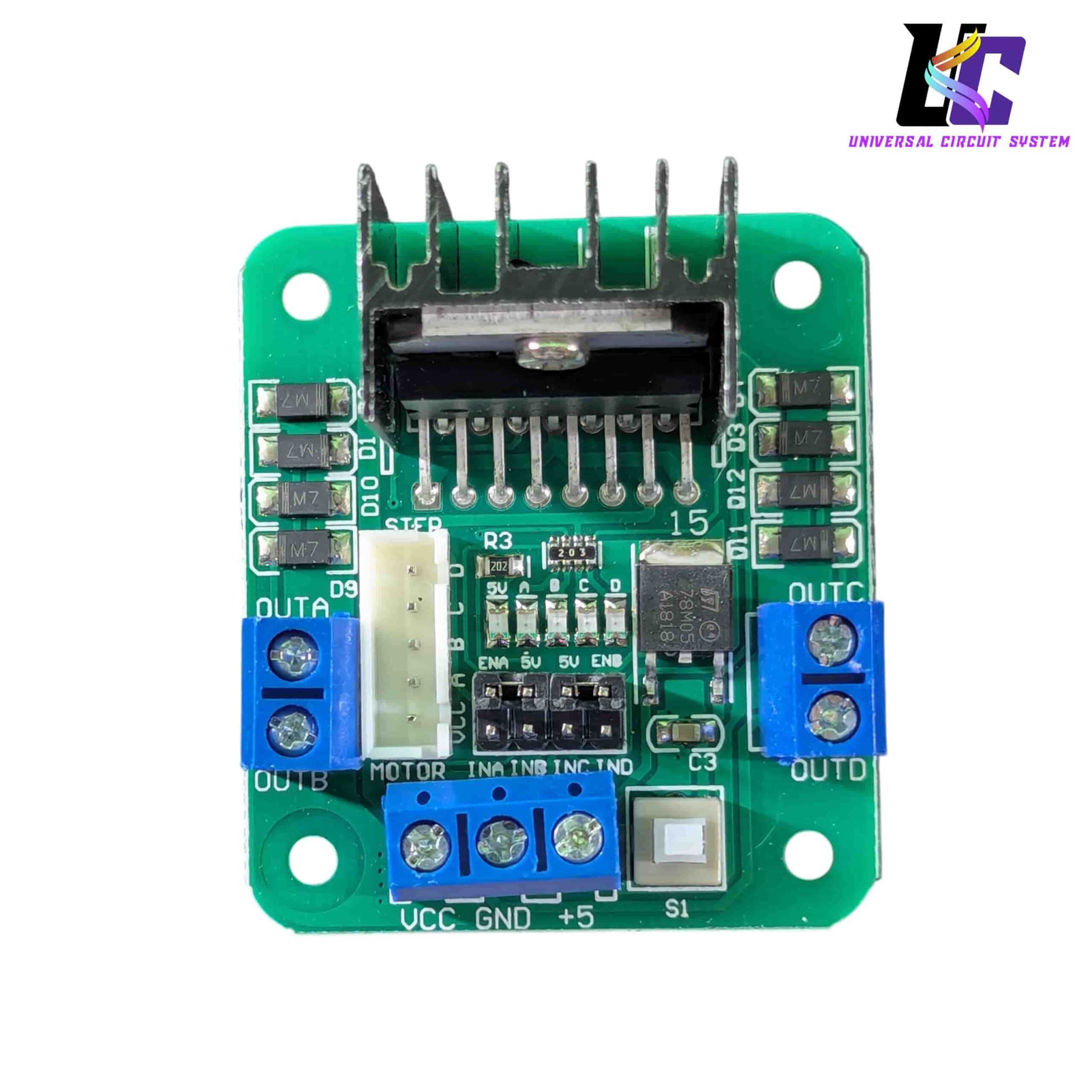
* Onboard 78M05 5V Linear Regulator: Features an integrated step-down regulator chip and a matching mechanical tactile slide switch labeled S1 [Image Context]. When operating your main motor drive voltage (VCC) between 7V and 12V DC, this onboard chip steps it down to generate a clean +5V output rail, allowing you to feed logic power straight back into your Arduino developer board without an external secondary supply block [Image Context].
* Heavy-Duty High-Voltage Screw Terminals: Outfitted with robust, industrial-grade blue screw terminal block interfaces [Image Context]. The output ports (OUTB and OUTD) cleanly pinch high-flux motor supply cables, while the power hub accommodates raw VCC, GND, and +5V lines without risk of pins fraying or vibrating loose [Image Context].
——————————
## Technical Specifications
| Geometric / Electrical Parameter | Verified Structural Dimension Value |
|—|—|
| Central Driver IC IC | STMicroelectronics L298N Dual H-Bridge Silicon Chip [Image Context] |
| Logic Supply Voltage Level | +5V DC nominal logical operational threshold [Image Context] |
| Main Motor Drive Voltage Range | DC 5.0V up to 35.0V Maximum (VCC Input Channel) [Image Context] |
| Peak Current Load Limit | 2.0 Amperes (2A) maximum continuous output per individual channel |
| Logic Current Consumption | Idling range from 0mA to 36mA |
| Peak Power Dissipation Capacity | Up to 25 Watts maximum thermal ceiling (with heat sink) [Image Context] |
| Control Signal Level Logic | High standard +5V DC |
——————————
## Terminal Configuration & Control Logic
* The Power Terminal Hub:
* VCC: Connects to the main motor battery or power supply (5V – 35V DC) [Image Context].
* GND: Central ground line linked to both the motor power source and the microcontroller ground [Image Context].
* +5V: Delivers a 5V logic supply line output (if the S1 switch is active and VCC is under 12V) or serves as a 5V input from an external logic source [Image Context].
* The Logic Control Headers: Features a multi-pin jumper array to process directional signals:
* IN1 & IN2: Drives the directional logic states and PWM speed parameters for Motor Output Port A (OUTB) [Image Context].
* IN3 & IN4: Drives the directional logic states and PWM speed parameters for Motor Output Port B (OUTD) [Image Context].
* ENA & ENB: Speed enable pins. Removing the pre-installed black jumper caps opens up these ports to receive direct Pulse-Width Modulation (PWM) speed tuning frequencies from your microcontroller.
——————————
## Common System Deployments
* Smart Robotic Toy Cars: Serving as the central locomotion engine room behind 2-wheel drive (2WD) and 4-wheel drive (4WD) obstacle-avoiding rovers and line-tracking competition chassis kits.
* Automated CNC and 3D Printer Axes: Driving medium-sized NEMA 17 stepper motors or high-torque DC lead screw motors inside desktop fabrication tools.
* Solenoid & Relay Multiplexing: Operating arrays of high-voltage electromechanical coils, industrial valves, and multi-stage latch relays away from safe microcontroller logic channels.




Reviews
There are no reviews yet.