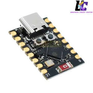
ESP32-C3 SuperMini Development Board
Roll over image to zoom in
৳ 500.00৳ 650.00 (-23%)
This ESP32-C3 SuperMini Development Board is an ultra-compact, high-performance IoT microcontroller board designed for space-constrained wearable projects and smart home automation. Powered by a single-core 32-bit RISC-V processor, this micro-sized board features integrated 2.4 GHz Wi-Fi and Bluetooth 5 (LE).
This ESP32-C3 SuperMini Development Board is an ultra-compact, thumb-sized IoT microcontroller board engineered to deliver high-performance processing and robust wireless connectivity within space-constrained applications. Built on a cutting-edge single-core 32-bit RISC-V architecture, this micro development board combines computing efficiency with low power consumption, making it an essential building block for smart wearable devices, remote sensor arrays, and compact smart home automation nodes.
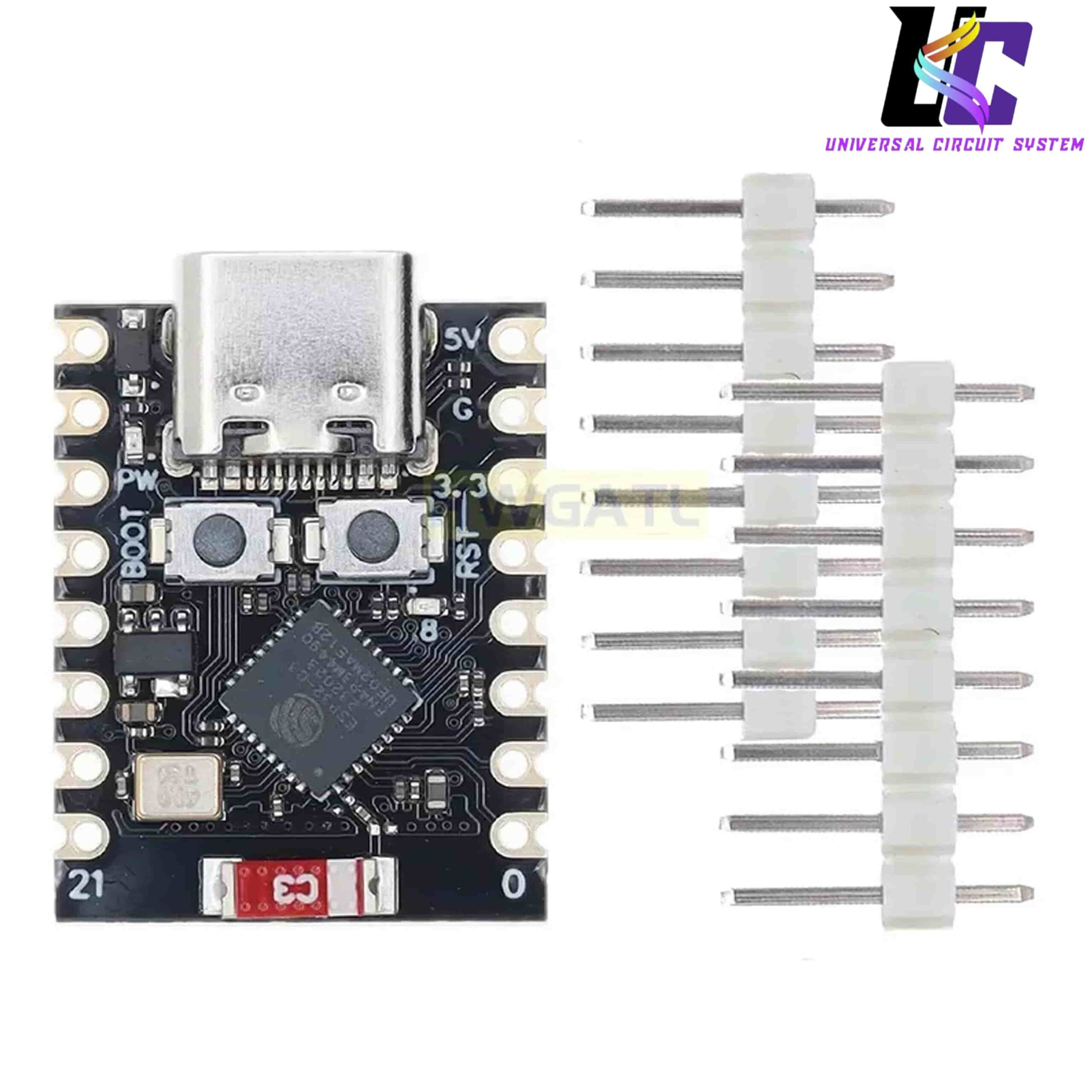
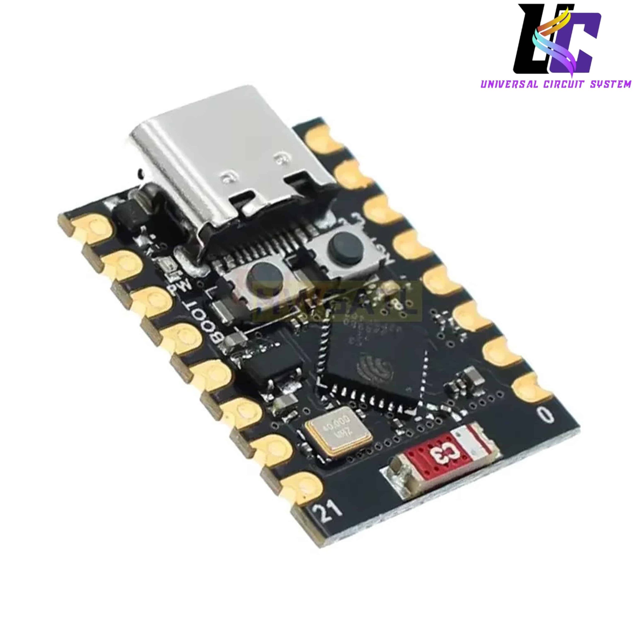
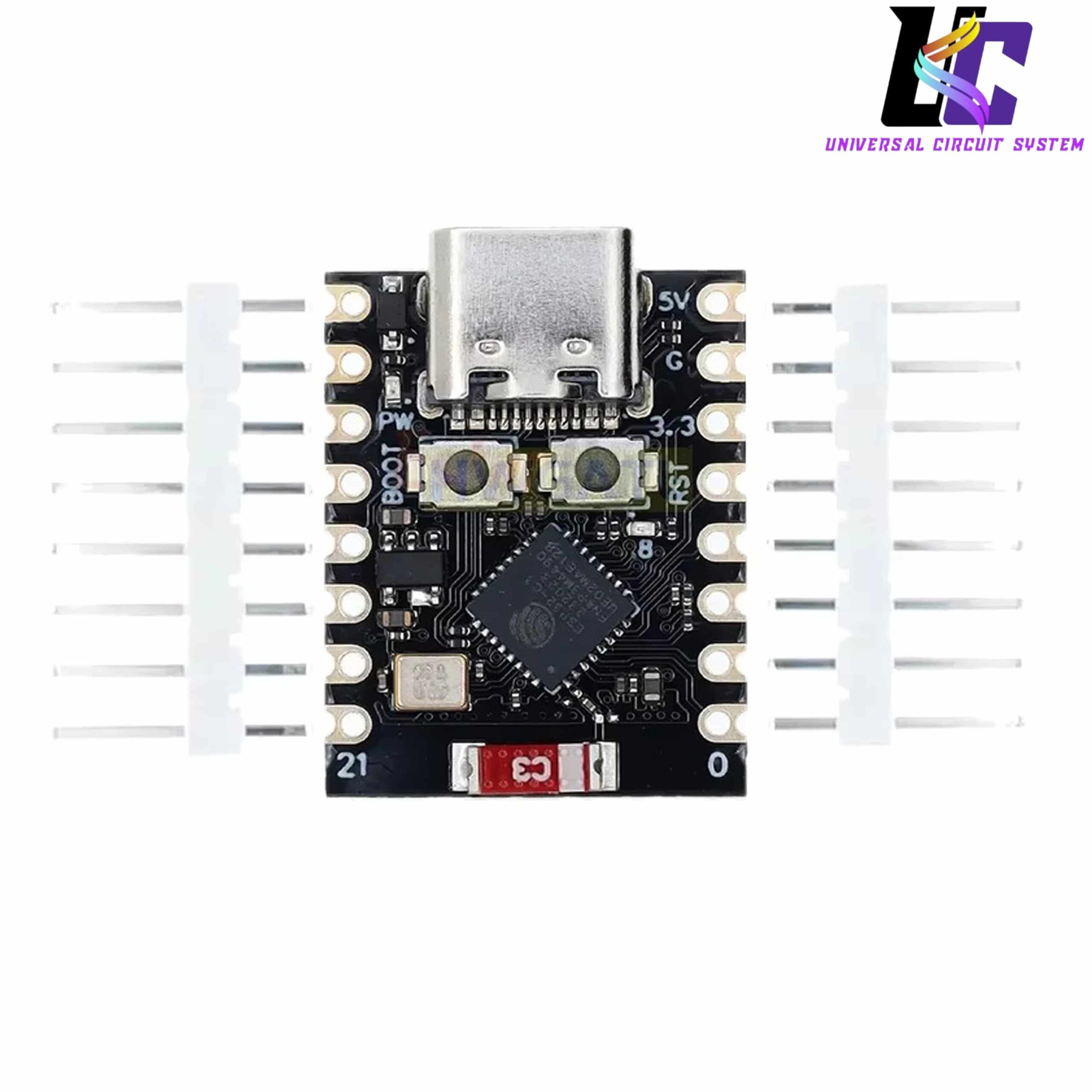
Despite its minuscule footprint, this module balances a rich array of hardware peripherals with dual-wireless communication capabilities, packing integrated 2.4 GHz Wi-Fi and Bluetooth 5 (LE) onto a high-density black PCB. The board features a modern, reversible USB Type-C port for seamless power supply and firmware flashing, alongside dedicated tactile buttons for rapid troubleshooting. It comes bundled with two un-soldered male header pin strips, allowing developers to choose between low-profile direct-wire soldering via the castellated edge pads or standard breadboard-ready header configurations.
Technical Specifications
- Core Processor: Espressif ESP32-C3 (Single-Core 32-bit RISC-V microarchitecture)
- Clock Frequency: Adjustable up to 160 MHz
- Memory Architecture: 400 KB SRAM, 384 KB ROM, and 4 MB onboard SPI Flash
- Wireless Ecosystem: 2.4 GHz Wi-Fi (802.11 b/g/n) + Bluetooth 5.0 Low Energy (BLE)
- Onboard Antenna: High-gain surface-mount ceramic chip antenna
- Operating Logic Voltage: 3.3V DC (All I/O pins are 3.3V logic tolerant only)
- Power Supply Inputs: 5V DC via USB Type-C interface, or 5V/GND via dedicated header pins
- Physical Layout Features: Onboard Power LED (PW), Boot button, Reset button (RST), and castellated solder holes
- Dimensions: Ultra-miniature footprint (~22.5mm x 18mm)
Hardware Peripheral Matrix
- Digital I/O Ports: 11 x General Purpose Input/Output (GPIO) pins
- Analog Interface: 12-bit Analog-to-Digital Converter (ADC) channels
- Serial Interfaces: Supported protocols include I2C, SPI, UART, and I2S hardware engines
- PWM Channels: Integrated LED PWM controller for smooth dimming and servo motor control
Key Product Features
- Next-Generation RISC-V Core: Driven by an open-source single-core 32-bit RISC-V processor that delivers highly efficient computing pipelines and superior clock performance compared to older generation 8-bit or 32-bit architectures.
- Dual Wireless Connectivity Stack: Houses a unified 2.4G Wi-Fi station/softAP engine and a Bluetooth Low Energy 5.0 transceiver network, enabling your custom IoT devices to connect to home routers or communicate directly with smartphones.
- Castellated Edge & Header Flexibility: Built with dual-purpose castellated edge pads that allow the board to be soldered flat as a surface-mount module onto a larger custom PCB, or fitted with the included male pin headers for breadboard prototyping.
- Streamlined Twin Boot & Reset Logic: Equipped with separate onboard physical tactile switches (BOOT and RST). This layout simplifies deep-level firmware modifications, partition clearing, and code resets during hardware debugging phases.
- Cross-Platform Software Support: Fully compatible with mainstream open-source development ecosystems. Developers can write code seamlessly using the Arduino IDE, MicroPython, or Espressif’s native ESP-IDF framework.
Firmware Flashing and Bootloader Access Guide
To prevent customer support questions regarding flashing issues, consider adding this operational checklist to your product page:
- Entering Bootloader Mode Manually: If your computer’s compiler fails to automatically put the board into programming mode, press and hold down the BOOT button. While holding it, click the RST (Reset) button once, then release the BOOT button. The chip will enter its built-in ROM bootloader, allowing the software to write the new firmware over the USB-C link.
- Logic Voltage Warning: The input pins on this board operate strictly on a 3.3V maximum threshold. Connecting 5V sensors or data lines directly to the GPIO pins without a logic level converter can permanently damage the core processor chip.







Reviews
There are no reviews yet.