
Micro Switch Pinout Guide


Roll over image to zoom in
৳ 35.00৳ 45.00 (-22%)
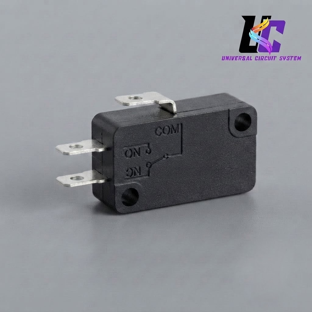
This miniature snap-action micro switch features a standard Single Pole Double Throw (SPDT) configuration, making it a highly versatile component for precise circuit control. Encased in a durable, flame-retardant plastic housing with dual integrated mounting holes, it utilizes a quick-acting top plunger that minimizes internal arcing and extends component life. The side of the casing features a clear, molded schematic detailing its three quick-connect spade terminals: COM (Common), NC (Normally Closed), and NO (Normally Open). It is ideal for 3D printer limit switches, appliance safety interlocks, and robotics projects.
If you are setting this up, let me know:
-
- Your circuit’s operating voltage and current
- The pins you plan to connect to your microcontroller (if applicable)
- If you need help choosing between the NC or NO paths for your specific logic
Micro Switch Pinout Guide
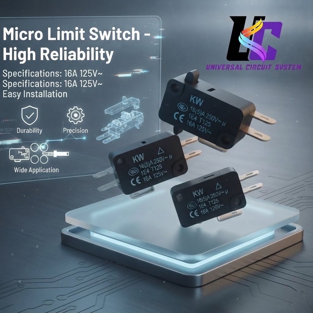
This Miniature Snap-Action Micro Switch is a high-performance, precision-engineered electromechanical component designed to deliver exceptional reliability and extended operational life in demanding electrical and mechanical control systems. Operating as a Single Pole Double Throw (SPDT) switch, this versatile device offers dual-path circuit routing. It serves as an indispensable building block for engineers, technicians, and makers working across industrial automation, robotics, and consumer electronics.

Micro Switch Pinout Guide
Robust Construction and Mechanical Design
The outer casing of the micro switch is molded from premium, high-impact industrial plastic. This housing provides excellent mechanical durability and elevated thermal resistance, ensuring consistent performance even under heavy structural stress or localized temperature spikes. Additionally, the material features flame-retardant properties to maintain strict electrical safety profiles within crowded control panels or enclosed appliance chassis.
The compact geometric body incorporates two integrated mounting holes. These through-holes allow for secure, vibration-resistant fastening using standard machine screws, preventing physical shifting or misalignment during high-frequency mechanical operations. At the top of the unit sits a distinct, highly tactile plunger actuator.
Internally, the switch utilizes an advanced snap-action spring mechanism. When a specific operating force hits the top plunger, the internal electrical contacts instantaneously snap between positions, completely independent of the physical speed at which the plunger is being pressed. This rapid transition minimizes electrical arcing, prevents localized contact pitting, reduces electromagnetic interference, and significantly extends the component’s overall electrical duty cycle.
Micro Switch Pinout Guide
Clear Terminal Architecture (Pinout)
The switch features three prominent, silver-plated spade or quick-connect terminals extending from its rear and lower base. These pins accommodate fast slide-on crimp connectors or direct wire soldering. To eliminate wiring errors during assembly, a crisp, tactile schematic diagram is engraved directly into the plastic sidewall of the casing, explicitly detailing the internal logic and terminal assignments:
-
- COM (Common Terminal): The central anchor of the switch circuit. The incoming current from the power supply enters through this terminal before being routed dynamically to either of the two output lines.
- NC (Normally Closed Terminal): In the default resting state—when no external force is acting upon the plunger—the internal mechanism maintains a direct electrical bond between COM and NC. This configuration allows a continuous flow of current to downstream components until the switch is intentionally triggered to cut the power.
- NO (Normally Open Terminal): In the default state, this channel remains entirely isolated and broken from the common line. The moment the top plunger is depressed past its physical trip point, the internal contacts snap instantly, severing the NC path and closing the connection between COM and NO to activate the secondary sub-circuit.
Micro Switch Pinout Guide
Versatile Engineering Applications
Thanks to the foundational flexibility of the SPDT contact arrangement, this micro switch functions seamlessly in a broad spectrum of automated sensing and safety environments:
-
- Endstop Limit Switching: Extensively deployed in 3D printers, CNC milling machines, and linear actuators to detect physical boundaries. It signals the control board that an axis has reached its maximum travel threshold, preventing mechanical collisions.
- Safety Interlock Mechanisms: Integrated into domestic appliances like microwave doors, washing machines, and industrial blenders to ensure the machine cannot power on unless the access panel or lid is fully closed and locked.
- Robotic Contact Sensing: Used as a reliable bumper sensor in autonomous robotics, allowing mobile units to detect physical collisions with walls or obstacles and immediately execute evasive navigation algorithms.
Combining space-saving dimensions with rugged electrical endurance, this micro switch is a dependable choice for building, upgrading, or repairing complex electromechanical hardware.
If you are currently configuring this component for a build, let me know if you need help with resistor calculations, matching the voltage/current tolerances, or designing a microcontroller debouncing circuit.




Reviews
There are no reviews yet.