
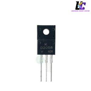
FQPF20N60C N-Channel Power MOSFET Transistor


Roll over image to zoom in
৳ 33.00৳ 50.00 (-34%)
The FQPF20N60C is a high-performance N-Channel enhancement-mode power MOSFET designed for high-voltage, high-speed switching applications. Housed in a fully isolated TO-220F plastic package, this power transistor is rated for a breakdown voltage of 600V and a continuous drain current of 20A. It utilizes advanced planar stripe DMOS technology to achieve exceptionally low on-state resistance (\(R_{DS(on)}\)), minimized gate charge, and high ruggedness against voltage surges. This makes it an ideal, dependable component for switched-mode power supplies (SMPS), electronic ballast regulators, active power factor correction (PFC), and standard DC-to-AC power inverter circuits.
FQPF20N60C N-Channel Power MOSFET Transistor (TO-220F)
Product Overview
The FQPF20N60C is an advanced N-Channel enhancement-mode power field-effect transistor engineered with proprietary planar stripe and DMOS technology. This specialized semiconductor is custom-tailored to minimize on-state resistance ($R_{DS(on)}$) while providing high avalanche energy strength and swift switching speeds. Packaged in a fully insulated TO-220F molded chassis, it safely isolates the internal substrate from external mounting hardware, eliminating the need for separate insulation sheets in dense circuit layouts. [1, 2, 3, 4]
Key Features
- High Voltage Tolerance: Built to manage high-stress voltage thresholds with a reliable 600V to 650V drain-source breakdown capability.
- Robust Load Handling: Supports up to 20A of continuous drain current under typical baseline operating conditions. [4, 5]
- Ultra-Low On-Resistance: Uses planar stripe geometries to maintain minimal resistance, effectively limiting power losses and thermal buildup.
- Minimized Gate Charge: Low gate charge (typically $Q_g$) ensures faster switching frequencies and less demanding gate-drive power consumption.
- 100% Avalanche Tested: Factored to withstand rugged voltage spikes and reactive energy feedback caused by inductive loads.
- Fully Isolated TO-220F Enclosure: Features a plastic overmolded tab that reduces the risk of accidental electrical shorts directly to external heatsinks.
Technical Specifications
| Parameter | Specification Rating |
|---|---|
| Transistor Type | N-Channel MOSFET |
| Package Outline | TO-220F (Isolated Plastic Package) |
| Drain-Source Voltage ($V_{DS}$) | 600V – 650V Maximum |
| Continuous Drain Current ($I_D$) | 20A Max (@ $T_C = 25^\circ\text{C}$) |
| Pulsed Drain Current ($I_{DM}$) | 53A Peak Surge |
| Gate-Source Voltage ($V_{GS}$) | ± 30V Limits |
| Operating Temperature ($T_J$) | -55°C to +150°C Range |
Terminal Pin Configurations
Looking directly at the front branded faceplate of the TO-220F package with pins pointing downwards:
- Pin 1 (Left): Gate (G) — Receives the voltage control signaling.
- Pin 2 (Center): Drain (D) — Connects directly to the main circuit load track.
- Pin 3 (Right): Source (S) — Connects to the ground loop return line. [3, 4]
Ideal Applications
- Switched-Mode Power Supplies (SMPS) for servers, telecom, and consumer electronics.
- Active Power Factor Correction (PFC) power supply circuits.
- High-frequency DC-to-DC converters and step-up boost modules.
- DC-to-AC power inverters and solar PV off-grid energy storage tracking.
- Electronic fluorescent lamp ballasts and solid-state welding machine output stages. [1, 4, 6, 7]





Reviews
There are no reviews yet.